Hardware
Description of the hardware of the robot.
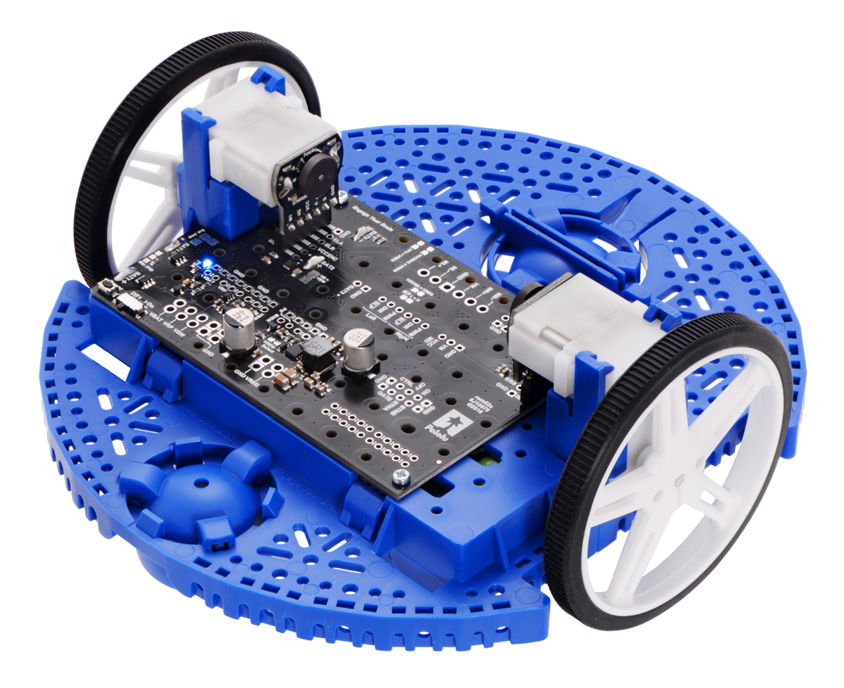
Base Chassis
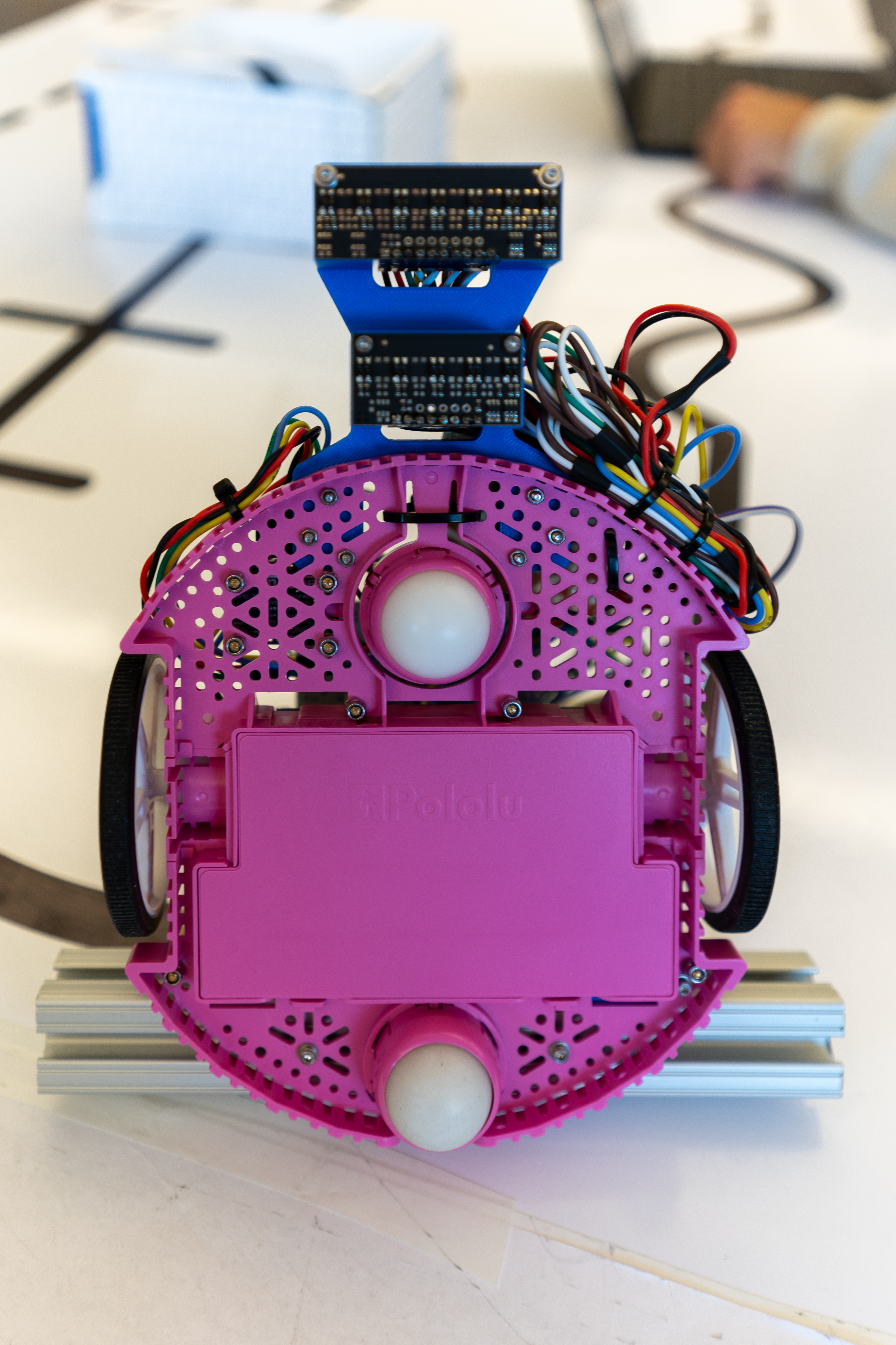
The chassis is a Pololu Romi (https://www.pololu.com/category/202/romi-chassis-and-accessories). We are using the Motor Driver and Power Distribution Board for the Romi Chassis (https://www.pololu.com/product/3543) to get regulated voltage from 6xLR6 batteries, and drive the 2 DC motors with the included TI DRV8838 motor drivers.
Processor
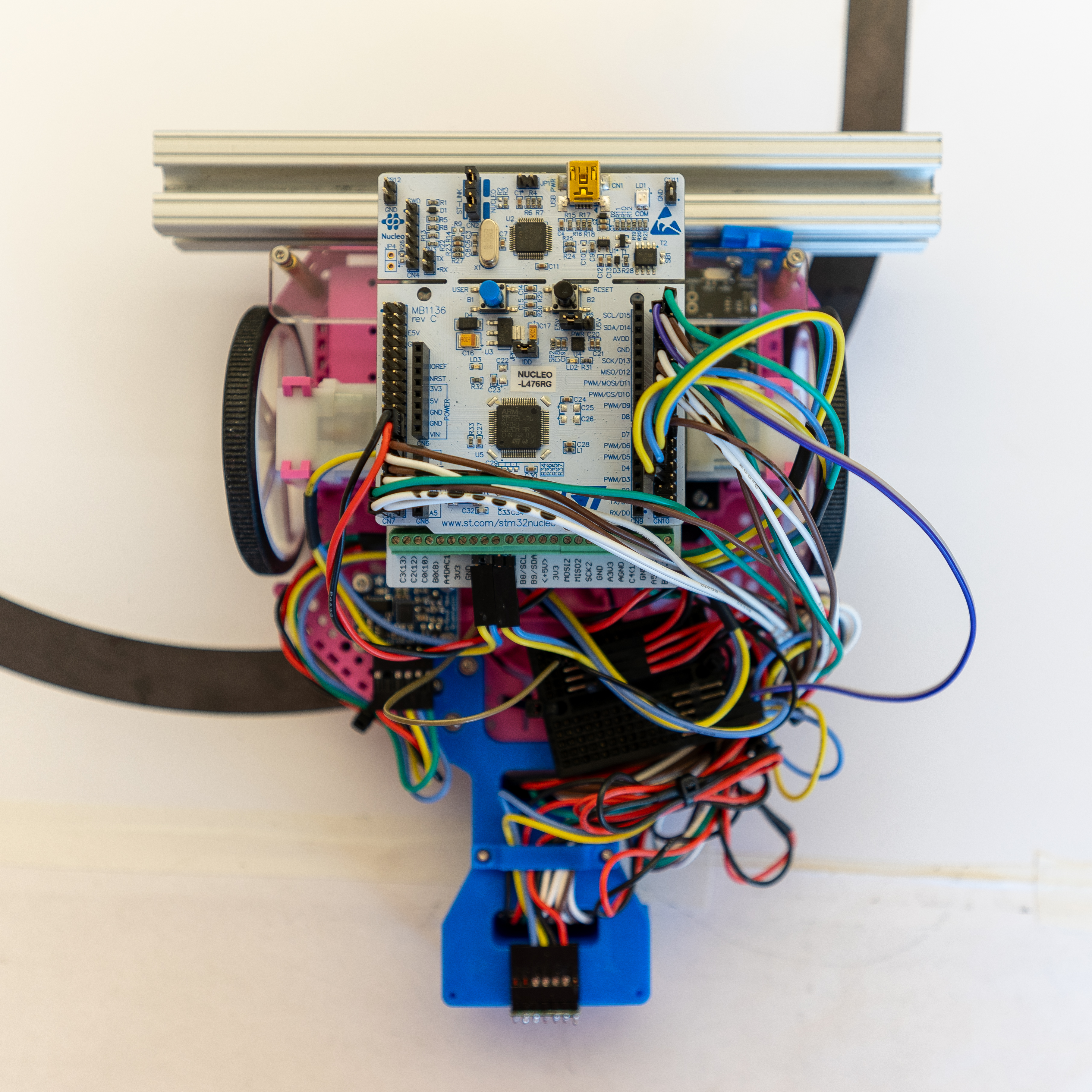
This robot uses a Nucleo-L476RG, which has an STM32L476RG from ST Microelectronics. It is running Micropython, using the firmware.bin binary provided at https://github.com/spluttflob/ME405-Support/.
It is being used in conjuction with a Shoe of Brian (https://spluttflob.github.io/ME405-Support/shoe_info.html) to provide a native USB port for use with Micropython code.
Sensors
We are using the rotary encoder kit for the chassis (https://www.pololu.com/product/3542) for our positional feedback. In combination with a Bosch BNO055 Inertial Measurement Unit (IMU), we can get a relatively accurate (+/-1mm/minute) position using dead-reckoning of encoder distance traveled in the current IMU heading.
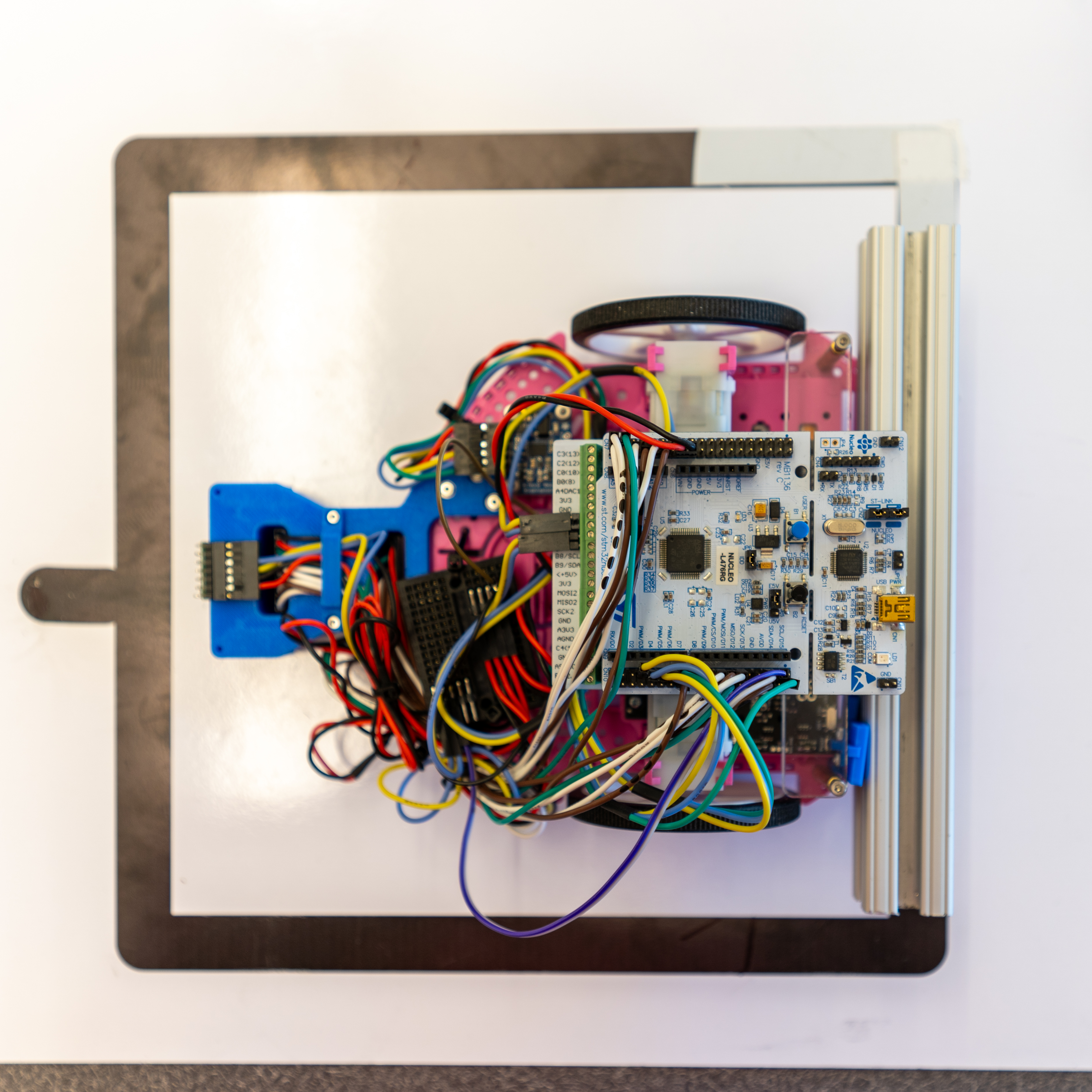
For line following, we are using Pololu QTR infrared reflectance sensors (https://www.pololu.com/category/123/pololu-qtr-reflectance-sensors). Specifically, we are using one QTR-MD-07A and QTR-MD-05A. They are aligned (see Bottom view photo below) horizontally respect to the Y axis, but placed spaced out in X at a distance such that one of the sensor arrays will always be on a dashed line. The mount for this is 3D printed from PLA, and is viewable on the CAD file link below.
To avoid the wall in the middle of the photo, we are using a ST Microelectronics VL53L1X time-of-flight sensor on a carrier board from Pololu (https://www.pololu.com/product/3415). This is attached to the front of the robot.
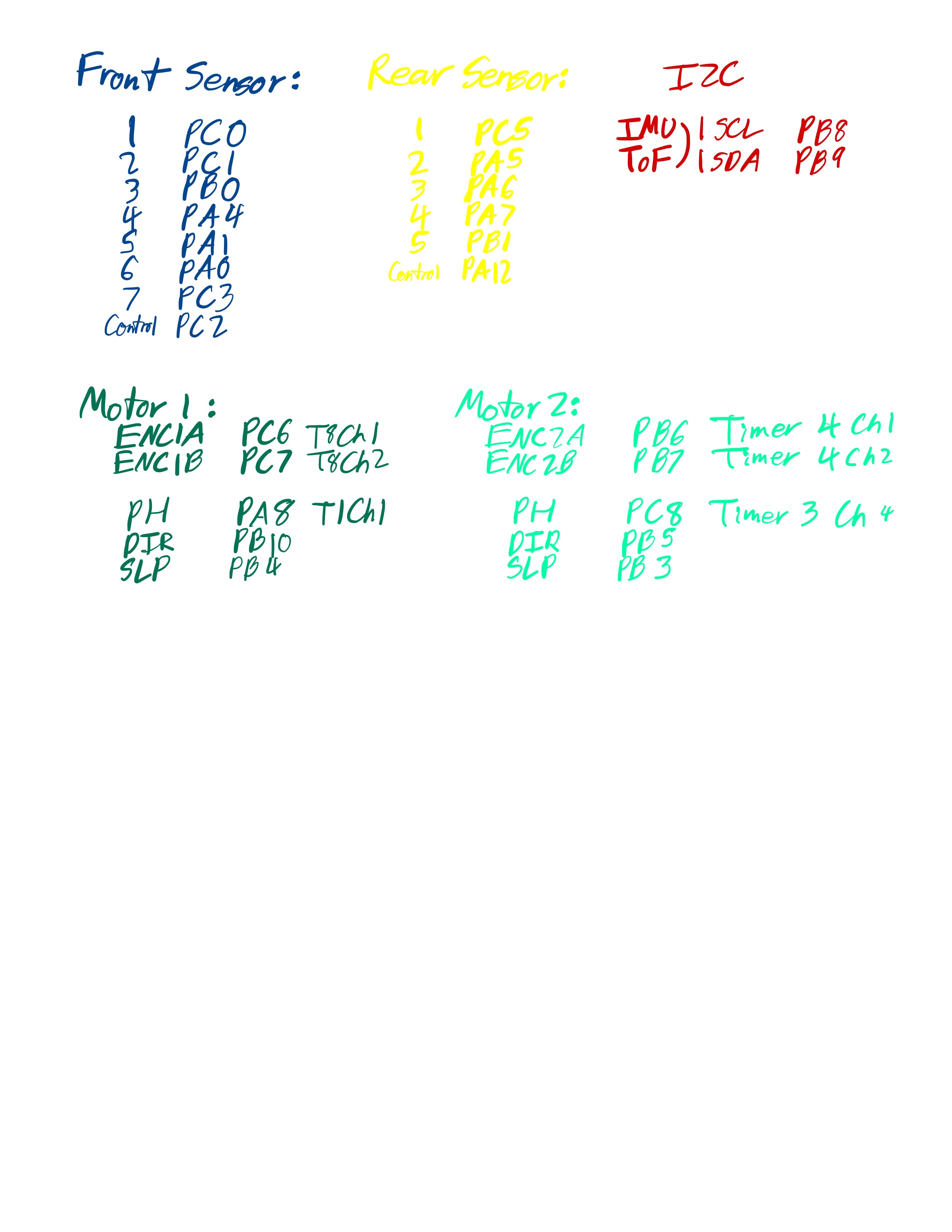
Wiring/Pinouts
Here is a diagram and table that explains how each of the sensors are connected to the Nucleo development board.
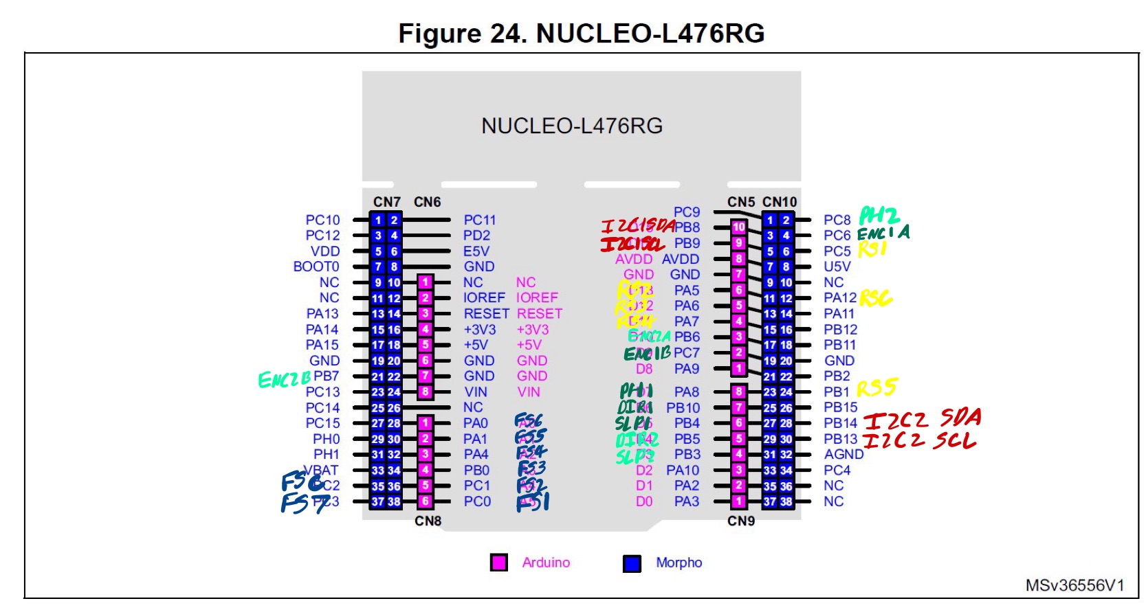
And this explains the pin labels:
Coordinate System
We are using a standard 3-axis coordinate system, where the front of the robot points in the positive X direction, and the central pivot axis is the positive Z axis. Here is a descriptive photo of the coordinate system of the track:

CAD
For CAD reference (ex. reflectance sensor mount), please use the Onshape link:
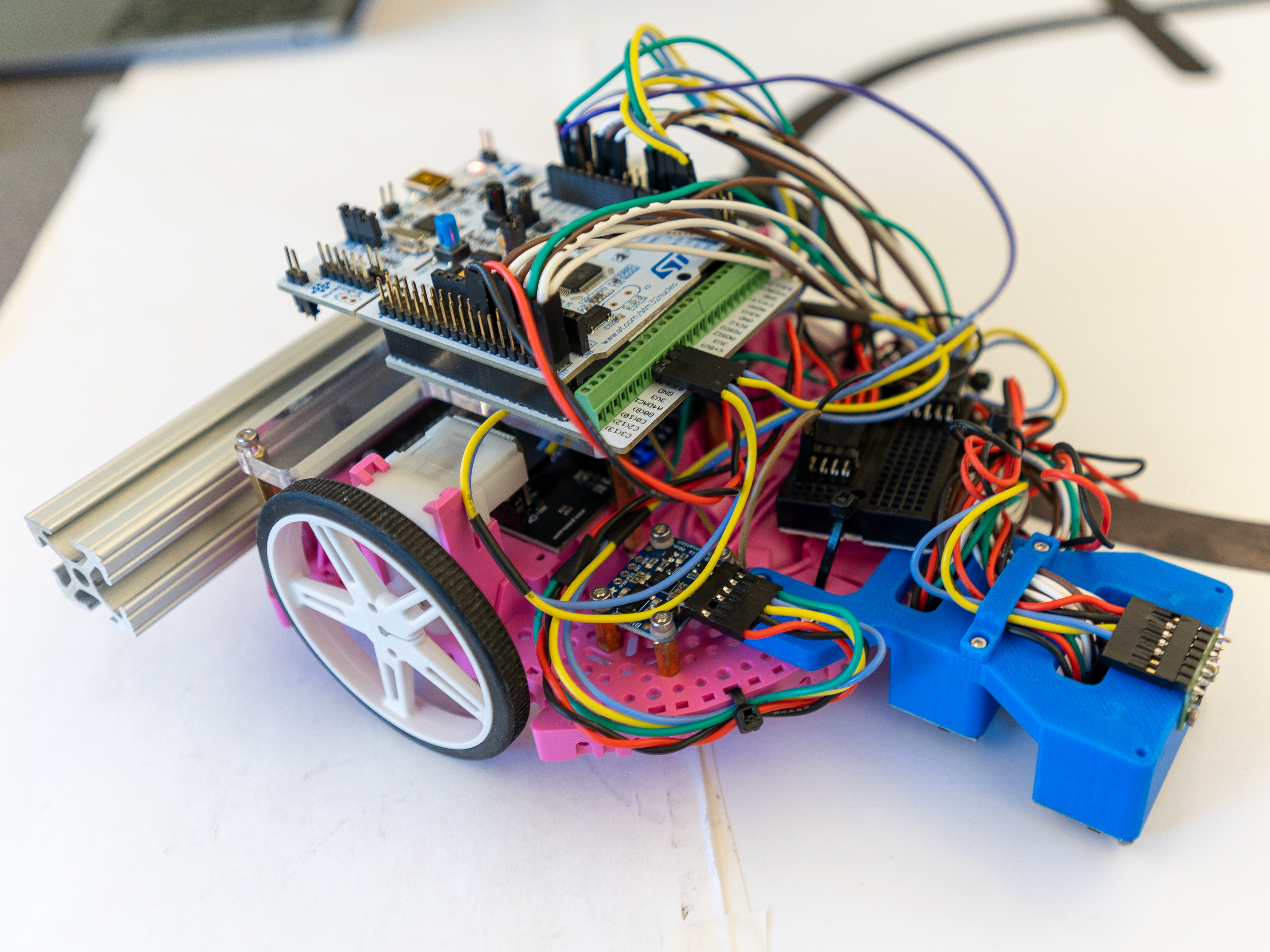
Photos